Sunday, 30 June 2013

The Coil is done and tuned!


Finally after weeks of work its finished. After it working the first time i decided to really tune it. I re did the math and found out that i was doing the calculations on 60hz but in england wall power s 50hz. After redoing all the math i overhauled the coil and remade most of it including:


  • New bigger primary
  • Extended Secondary
  • Made the base more secure
  • Added two more capacitors
  • Re made the spark gap three times
  • Made a bigger topload

The coil is epic now and iv even added a breakout point to get even bigger sparks. Look at this new video to see it in action - http://www.youtube.com/watch?v=b2C-AZAz51E

Wednesday, 5 June 2013

Update!


We have first light people! Here is a good project video I made about it. When the coil is tuned it will be a LOT better! - http://www.youtube.com/watch?v=t3C0uY1gRMc

Tuesday, 28 May 2013

Progress!

We have progress! The new step down transformer we ordered has came and with a little bit of wiring its working! Once again we made a jacobs ladder using it and managed to test the cap bank. Unfortunately the bank failed so I need to do another test to find out why but thats for later. For now, we are set and one step closer to running the coil proper!

Sunday, 26 May 2013

Running Your Tesla Coil

Ok so I have not ran my coil proper yet but i have tested the transformer and we do have first light! The step down transformer had a too low wattage and blew so it has halted construction. MAKE SURE YOUR STEP DOWN CAN TAKE THE WATTAGE OF THE NEON SIGN TRANSFORMER. i'll try and put the video of it on youtube.

Next: Running the Tesla Coil 2

Saturday, 25 May 2013

Testing Components


You're so close to running it for the first time but first you need to check all of the components!

First check the transformer by plugging it it and trying to create a spark between both terminals using a piece of wire. This will not damage it don't worry.

 Then test the safety gap and make sure that the spark does NOT jump from one terminal to the middle one. If nothing happens then it is working. 

Test the cap bank by plugging up one end of it to the transformer and the other try and ark to the other terminal of the transformer. 

Finally check the spark gap, make sure the spark jumps between the two terminals. 

After you have done all of these and everything works you're ready to run it proper.!

Next: Running the Tesla Coil

Connections

Now to connect everything up. It really easy. All you need is some simple crocodile clip wires and follow the diagram.


All the stuff on the left is the transformer. Everything else is clearly labeled and just wire up everything just like seen here. If your tesla coil uses a safety gap then put it in parallel to the two outputs of the transformer like the caps are. But make sure its the first thing the transformer gets too. Assemble, glue, tape and connect everything together and you should have something looking like this.


All your circuitry should be at the bottom hooked up to the main tower assembly at the top. Now its time to test the components!

Next: Testing components

Friday, 24 May 2013

Step down transformer

If you live in england but your transformer is american (vice versa) then there is a voltage difference and you will need a step up/down transformer to fix the problem. All you need to do is to buy one that the input fits your country and the output fits the transformer. This step is easy but necessary if there is a voltage difference.


Next: Connections

Monday, 20 May 2013

Grounding Rod

The grounding rod is an essential piece of the tesla coil yet it is very simple to make and use. All you need to do is shove a metal pole as deep into the ground as you can. This is needed for your tesla coil to work safely and if you have a safety gap like me you need somewhere to vent the feedback. 


To make it work, just make a wire coming from the neon sign transformer ground terminal, the bottom wire of the secondary coil and the grounding terminal of the safety gap to the grounding rod when you run the transformer. This will make everything work properly!

Next: Step down Transformer

Capacitor Bank

The capacitor bank and primary coil make up the primary circuit for the tesla coil. Now if you have done the math correctly in one of the first steps you should know which capacitors your using, how many of them in a string and how many parallel strings there are. If you do not know this re-read the maths steps. If you are making a tesla coil the same as mine you will need 9 of these in series with only one string.

http://www.ebay.co.uk/itm/1250V-0-15uF-POLYPROPOLENE-CAPACITOR-WITH-METAL-FILM-ROHS-COMPLIANT-NEW-/400337027811?pt=UK_BOI_Electrical_Components_Supplies_ET&hash=item5d35f242e3


This step is not hard; all you need to do is make something to hold your components  on and do some wiring. I suspended a piece of balsa wood by 1cm high dowels and on the wood would be the circuitry for the bank. Once you have that you need to solder the wires. Put one of the resistors i put in the parts list between each cap and just wire then in series or parallel depending on what your maths tells you. My one just had all nine caps in a string one after the other with a resistor after each one. Don't bother connecting the start and the end of the string to anything yet. 


Once this is done, stick the bank to the main frame of the tesla coil ready to be hooked up in a later step.

Next Step: Grounding Rod

Sunday, 12 May 2013

Neon Sign Transformer/ Update

Ok so its been a while. Sorry I have been distracted by many things and getting the NST was a NIGHTMARE.

To help you all out this post will explain how to get a neon sign transformer/NST.

Modern day NST's have a GFCI chip in them that basically make making tesla coils or anything else with them very very difficult. Thats why people say get older NST's as they don't have the chip in. Now in england its impossible to get an NST that does not have the GFCI in. It is possible to buy one and take the chip out but its hard and if done wrong can kill the transformer. The only way to get one will be to order one of ebay coming from america and with there outrages weight, the shipping charge is about £100!. This is why it took me ages to get one as I was looking for one that was cheap. If you live in america its fine but if not I advise going here. There shipping charges are cheaper but still quite expensive.


The website is great for high voltage projects including jacobs ladders, rail guns and lasers. (Might be my next project)


I got the 6kv one. Any way that is why this project has not been updated in awhile so thanks for being patient!

Next: Capacitor Bank

Sunday, 10 March 2013

The Secondary Coil

The secondary coil and the topload makes up the secondary circuit. This part is the easiest to do but defiantly the longest, most tedious and the most boring to do. All you have to do is coil your magnet wire round your tube. If you are using the same ratings as mine you need to wrap hair thin wire around a half meter long 10cm radius tube. Takes a VERY long time!


 The easiest way to do it is put a pipe through your tube and put each end of the pipe on a chair. Then use one hand to turn the tube and the other to guide the wire. 


Once done, sand about 3cm around each end of the wire and just leave the ends to hang. Then paint the whole thing in 2-3 coatings of clear varnish or clear coat.

Finished, varnished, secondary!
Next Step: Capacitor Bank

Thursday, 7 March 2013

The Primary Coil

The Primary Coil is one of the two parts that makes up the primary circuit. This is the high voltage exposed coil so DO NOT touch it when the coil is on. Now you can use a normal wire for the primary but it is better if it is a copper tube. This part is harder than it looks as getting and securing the tube in place without it moving is not easy. I did it by cutting holes in pipes and sticking the pipes with supper glue onto the coil base I made in the first step. You can just drill holes in the wood as it would be easier but I did not have a drill at hand so I used my solder to burn through the plastic pipes.
Pipes stuck on to frame
with coil ready to be added.


Pipe with holes in.

Now just thread the primary coil tube through the holes to make the pancake shape we need. Don't forget to use the measurments in the CAD program when making the primary. If you are making one with the same ratings as mine you will need 5 meters of this

http://www.ebay.co.uk/itm/NEW-4mm-microbore-copper-plumbing-pipe-tube-x-1-Metre-/110522134268?pt=UK_DIY_Materials_Plumbing_MJ&hash=item19bba1eefc

Tapped between turns 6-7.

AS this wire is not very malleable you will need to put the pipes on the coil of wire BEFORE you glue it to the wooden base. It takes a long time but it can be done with some patience. 


Next Step: The Secondary Coil

Wednesday, 6 March 2013

The Safety Gap

The Safety gap IS NOT THE SAME as the spark gap!

The safety gap is a basic component used for high voltage Tesla Coils only. It is basically a way to protect all the circuits components from a high voltage feed back. Sometimes a high voltage feed back comes back from the primary coil into the transformer burning it out and blowing out the caps. If the output spark from the coil hit the primary coil then the same would happen but worse. There would be no way to repair it you would need to buy new capacitors and a new neon sign transformer. The safety gap is a basic part that will prevent and feed back or arks from the primary from damaging any of the circuits components.

The safety gap is like a spark gap but there is never a spark going between the three terminals. Instead, if a high voltage is feed back or arks from the toroid, it will trigger the spark gap and both terminals will fire into the middle terminal. The middle terminal is grounded so all the power will be vented to ground keeping the circuits components safe. Just think of it as a spark gap that will only work when there is a really high voltage and when it does all that voltage is send straight to ground.

This component is OPTIONAL in you Tesla Coil; it is not required to run but it is advised that you do use one as a safety precaution.


To make it just put three screws in a line through wood making them relatively close, make sure only the middle one goes through the bottom of the wood. Cover both of the other screws in glue but no the screw head. This will make it so the spark can only ark out of the screw head and not the rest of it. Then just hook the safety gap in parallel with the transformer and hook the middle screw to ground (Preferably to an outside grounding rod). You gap should be good to go.


You can use the depth of middle screw to make the gap smaller or bigger.


Next step: Secondary Coil

The Spark Gap

If you know how a Tesla coil works then you will know what a spark gap is and what it does, if you dont I will now explain. The spark gap is a voltage controlled switch and is literally a very small gap about 1cm between one of the Tesla Coil wires. There needs to be a high voltage and if there is than the electricity will be able to jump the gap taking time. The Capacitors need time to fill up and discharge so this spark gap gives them it. The bigger the spark gap, the more time there is for the caps to fill resulting in a bigger output from the coil. I will be making a more advanced spark gap by housing it in a balsa wood tube with a fan at each end. The fans are set so one will suck and one will blow out. I have done this for two reasons:

  • Firstly because high voltage travelling through are creates ozone that needs to be vented.
  • Secondly because the spark can jump the gap easier if there is a lower air pressure and the fans should create this.
You dont have to have any fans you can just use two open ended wires but this one will work better and I already had the fans. The electrodes I used were just stainless steel screws. I used screws so i could turn one of them so i could control the size of the gap. This way I can change the gap size when ever I want and make the coil more efficient. I have also hooked up a switch box so I can turn on and off the fans when I want. I will also probably hook up other things to the switches such as turning on and off the coil itself.

I have already kind of explained how to make it. Just ajusd the size of the gap so it is at its larges before the spark not jumping and your coil will work well.


Wiring the switch to the fans.

As I have said; making the fans and switch is optional, having a spark gap is not. You must have one for the coil to work!

Next step: Safety Gap

The Topload

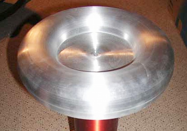
The topload is the big metal part sitting at the top of your coil. It can be spherical or toroidal or in lamens terms, a ball shape or a doughnut shape. Toroids are slightly better then a sphere though.


As cool as it looks, its not just for aesthetics. The topload actually acts as a capacitor, the topload as the first plate, the air being the dielectric and the ground or any other metal object it strikes being the second plate. As its a capacitor it builds up charge meaning there is a bigger output spark. The bigger and the SMOTHER the topload, the bigger the discharge will be.  

Now you can buy a spun aluminium toroid like in the picture above for about £50 or you can make one nearly as good for only  £15. All you need is that aluminium dryer ducked in the parts list and some foil pie plates.

First, cut a 1cm wide strip down  the whole length of the tubing. Then stick two pie plates together the top one being upside down kind of like a sourer shape. Wrap the dryer pipe around the pie plates making sure the edge of the pie plates go inside the strip cut for it. Finally, secure the two ends of the duck with tape or glue. Your toroid should now be ready to mount onto the secondary coil later.


Finished toroid laid out for the glue to dry.

Next step: Spark Gap 

Building the Frame

To make the setup compact, safer and easy to move, you will need to build a sort of frame to hold all of the parts of the Tesla Coil. You can put it all on 1 sheet of wood or if you Tesla is quite big like mine, have two wooden sheets, one above the other.
My Frame, dont mind the wires there just to help mark out where everything is going to go.


You will also need a frame for the primary and the secondary to sit on. You can do this by sticking together four small planks of wood in an X shape. Make sure you cut the wood long enough to fit the right amount of turns on it as stated in the CAD program. If the turns are too close together it is a problem as the electricity ca arc from one turn to another ruining the efficiency completely! I have also stuck a tub lid to my frame so it can hold my secondary.

My frame to hold the two coils. Marked with pen every 2cm there will be a turn.


You may want to mark out on the wood where everything is going to go so you can make sure you have enough space for everything. Also make sure you use strong glue to hold you supports to the wood because you don't want your coil collapsing half way through construction. Try and weight test it first before putting everything else on it.

Gorilla glue works well!


Now you can move on to the next step, making the topload!

Safety


Now that you have worked out all the necessary math and you have bought all the electronic part that should now match the math and create a efficient Tesla, its time to talk about safety!

Now we all know that electric fences have high voltage on and if you touched it it could kill you. But its not the voltage that kills you, its the current or amperage. But its the volts that deliver the amps. These transformers have a very high voltage but a very low current, only a few tenths of an amp. All of these transformer have the ability to kill you but that is only if you have a situation like both hands on the terminals, non rubber soles on your shoes and in a well grounded floor. If you just touched it with your finger tip with rubber soles on your shoes than you will feel pain but it wont do much damage.

The thing is that neither of them two situations should occur as the power should always be UNPLUGGED before going in to service it.  The power from the caps should be drained by the resistors (go into more detail later) so there should be no power left in the unit. Either way, always work with rubber gloves, rubber soles and make sure it is unplugged. The electricity can get through the rubber as it is at a very high voltage but it will slow it down a lot. Always check with a multimeter or other device to see if there is a live current. Finally once unplugged, leave the circuit for 30 - 60 seconds so the caps have time to bleed out. If you follow all this and be careful in everything you do you should be quite safe from any danger. 

But dont just take my word for it! Look online for more in depth safety tips like the one hand in pocket rule. Also look up more about grounding as I have not go over that topic. If all the part that need grounding are properly grounded then it will be safer to service.

Ok I think thats all that I can say about safety, now time to move on to finally building this thing!

Capacitance Math

Ok, so we know where to tap and how much capacitance we need but how do we choose what capacitors to buy? Well first of all you need to know what the peek voltage of your transformer and that is NOT the rated voltage on it as that is RMS voltage. To work it out just times the rated voltage by root 2.

6000v = 8485v Peek
10 000v = 14142v Peek
12 000v = 16970v Peek
15 000v = 21213v Peek

Now you MMC must accommodation for the peek voltage of your transformer. Now is the hard part. You need to find capacitors that if you add all of there voltages together, you get the same or higher than you peek voltage and they must have a total capacitance as close as the CAD program has told you. Any more capacitance and the circuit will be out of resonance. This is hard but here is a link to a online calculator that will work out the voltage and capacitance of your MMC. 

http://deepfriedneon.com/tesla_frame6.html

I am using 9 0.15uF 1250v caps all in series. If you type these in the calculator you will see that the total capacitance is near my needed 0.159uF and the voltage is not too high but still clears the peek voltage limit. Also you need to make sure that the caps total voltage does not go over 1.5 times that of the peek voltage or your circuit will have a voltage too high that can cause damage to the transformer.

I am using 9 of these caps -

http://www.ebay.co.uk/itm/1250V-0-15uF-POLYPROPOLENE-CAPACITOR-WITH-METAL-FILM-ROHS-COMPLIANT-NEW-/400337027811?pt=UK_BOI_Electrical_Components_Supplies_ET&hash=item5d35f242e3

If you are making a Tesla coil with the same ratings and speks as mine you can use these and the amount of them as I have already done the math for you when I was making my Tesla Coil.

Getting the right combinations of all these factors IS the hardest part of making a Tesla coil but when its done you will know you will have a good efficient Tesla.

Next: Safety then starting to build it!

Applying Maths

Doing math when making a Tesla Coil is very important as if you do your calculations right you can dramatically improve the performance of it by only spending a few more pounds. The great thing is that there is a program that will do all the math you need instantly  All you need to do is add some information of you electric components and it will tell you what you need to do to get the best output from what you have got. First thing first you need to decide what transformer voltage you are using.

Transformer

6000v or 6kv, 10 000v, 12 000v, 15 000v. These are the most used rating of neon sign transformers. I am only using a 6000v one because I am using the math to improve my tesla so i dont need to spend more money on expensive, bigger NST's. The more voltage you have in the transformer though the bigger the output spark. Also the current for these is only between 20 - 60MA so they wont kill easily. They do have the capability to kill you but only if you work for it. I will go more into safety later.

Secondary Coil

Now you need to decide on the size of the tube your magnet wire will be wrapped around. I am using a 10cm diameter and 50cm long cardboard poster tube. I will warp on 45cm down it so I have some space to work with. I also will be using this wire for my secondary.

http://www.ebay.co.uk/itm/ENAMELLED-WIRE-24-SWG-23-AWG-x-1-1-lbs-MAGNET-WIRE-/370769671928?pt=UK_BOI_Electrical_Components_Supplies_ET&hash=item56539836f8&_uhb=1

If your coil is smaller or bigger than mine buy more or less of the wire. You do not need to change the wire type as it should work for all Tesla Coils. May I just note that if you did not know the magnet wire is only conductive INSIDE the wire. There is actually a small coating of insulater on the wire so if you need to connect the ends of the wire to something else, sandpaper the end of it.

Primary Coil

The primary coil wire only has to be a conductive, flexible string of some kind. You can use a wire or like me, 5m of  flexible copper tubing found here:

http://www.ebay.co.uk/itm/NEW-4mm-microbore-copper-plumbing-pipe-tube-x-1-Metre-/110522134268?pt=UK_DIY_Materials_Plumbing_MJ&hash=item19bba1eefc

Doing the Math

Now that you have your measurements sorted you can go and download the program "Tesla Coil CAD" for free online. Just enter all your measurements and voltages and on the main screen you should see lots of text. In this text it will tell you the two main thing you need to know. Where to tap and the intended capacitance. These two measurements need to be implemented in your Tesla Coil for it to work as max efficiency.

Tapping is just basically how many turns you need to make the primary coil be. You need to get this right as too few turns will make the primary circuit under resonance but to many will result in over resonance. The primary and secondary circuits need to be in the same resonance then they will resonate and be efficient. If you dont understand resonance you need to look it up. If you are using my rating tap between the 6th and 7th turn.

Capacitance will be found under the Neon Transformer / Primary Capacitor Matching tab. There will be a number ending in uF. This is a measure of the capacitance needed to allow the primary circuit to be in good resonance with the secondary circuit. If you are using my ratings e.g 6000v transformer, 50cm long secondary then just use this capacitance: 0.0159uF. To meet this capacitance you either need to buy a capacitor with as high voltage as the peek voltage (tell you how to work out in the next step) and the same capacitance as the CAD program has worked out. Or you can make a MMC (Multi Mini Capacitor) which is a bank of small capacitors that will do the same job as a big one. Making an MMC is the easyest way and they way that I am going to do it.

Read on for : More math (Yey) making a capacitor bank and finally buying all the stuff you need now that you know the rating you need.

Introduction

To start off you need to learn how a Tesla coil works and the basic circuit diagram. You can do this by looking it up or watching related Youtube videos.


My coil will be a sligh variation to this; the spark gap and capacitors will swap places. Dont ask.


 You then need to decide on the ratings of the basic components e.g  what voltage you want to use, the size of you secondary coil. Once you have done that you can buy everything on the list below. This can be made in under £100 and cheaper if you live in America.

Note - Do not buy the things marked with "Check rating" until you completed the next step.


  • A Neon Sign Transformer - £50 -  From Ebay or Neon Sign shop - Check rating
  • Capacitors - £30 - Ebay or electronics shop - Check rating
  • 10 Meg Ohm Bleed Resistors - £9 - Ebay
  • Spark and safety gap materials - Can be anything from a few metal nails in a chunk of wood.
  • Spark gap fans - Optional
  • Switch - Optional
  • Crocodile clip wires - £3
  • Magnet wire 20AWG - Varies on size - Check rating
  • Flexable copper pipe - £3 for 1 meter - Check rating
  • Aluminium Air Ducting Flexable- £11, depends on size - Check rating
  • Cardboard or PVC tube - Check rating
  • Foil Pie Plates - £1
  • General wire - Lots of it needed for grounding!
  • Wood -  Flat plates and small short beams
These are the basic things you need to make a good working Tesla coil. Half of the things in the list you can not buy yet as you need to know the exact size, length or voltage of all of the things marked Check Rating before you can get them. If the ratings are wrong then the coil will not work as efficiently and you wont get the big sparks that we want! I will go over how to choose the sizes and voltages and the ratings I used in the next step. After that you can order the stuff in the size, voltage and other chosen parameters necessary.

About the Project


Not my pic!


The Nuclear Project has been put on hold as things have been getting the way of it but a new project has started. After Christmas I started and completed a small Tesla Coil project. It was more of a proof of concept that a small Tesla Coil could be made under 10 pounds with items found at home or bought on Ebay. I made one and here is what it looks like.


My first small Tesla Coil

Here is a link to the tutorial but you need to know more about tesla coils before you try this - http://www.youtube.com/watch?v=QDZnCOLZ394

New Project?

But I now have a new project. Since making this small Tesla Coil was fun and because it is quite small I have decided to embark on a project to build a much bigger one. It wont be as good as some online but it will be very fun to build and run and will look very impressive. The best part is that this blog will also act as instructions for you if you wont to make one of these your self and I guarantee you, by the end of this blog, you will!